


1. Introduction
In combustion applications, transient fuel jet injection controls ignition event timing. Flame ignition and subsequent stabilisation do not occur unless the right amounts of fuel and oxidiser are available at a given location. For example, in compression ignition engines, the ignition event occurs during the decelerating phase of fuel injection, as seen in figure 1. Controlling ignition timing is essential, considering that the time-dependent behaviour of the jet flow can lead to increased/decreased air entrainment (Hill & Greene Reference Hill and Greene1977; Bremhorst & Hollis Reference Bremhorst and Hollis1990). An improved mixing of fuel and oxidiser is sought, as this leads to enhanced heat conversion and reduced pollutant emissions (O’Connor & Musculus Reference O’Connor and Musculus2013). However, insufficient mixing causes incomplete combustion. It follows that optimising the injection process requires a solid understanding of unsteady mixing dynamics. This motivates the present investigation to tackle, using direct numerical simulations (DNS), the less investigated topic of turbulent mixing in unsteady jets, particularly decelerating ones.

Figure 1. Single cylinder optical engine transient fuel injection consisting, from left to right in chronological order, of a starting jet, a steady-state jet and a stopping jet, during which the ignition event happens (Gill et al. Reference Gill, Marriner, Sison and Zhao2005).
In compression ignition engines, the combustion mode takes the form of a turbulent non-premixed flame. This configuration is often modelled by two variables: mixture fraction (denoted as
 $\xi$
) and scalar dissipation rate (SDR, denoted as
$\xi$
) and scalar dissipation rate (SDR, denoted as
 $\chi$
). Mixture fraction is defined as the mass fraction that originates from one stream in a two-stream set-up. Typically, the two streams are fuel and oxidiser, such that
$\chi$
). Mixture fraction is defined as the mass fraction that originates from one stream in a two-stream set-up. Typically, the two streams are fuel and oxidiser, such that
 $\xi$
is considered unity at the inlet of the fuel stream, and zero at the oxidiser stream inlet. As fuel and oxidiser mix inside the combustion chamber, there will be a mixture fraction distribution. The flame can exist where the mixture fraction equals the stoichiometric mixture fraction value.
$\xi$
is considered unity at the inlet of the fuel stream, and zero at the oxidiser stream inlet. As fuel and oxidiser mix inside the combustion chamber, there will be a mixture fraction distribution. The flame can exist where the mixture fraction equals the stoichiometric mixture fraction value.
The second variable, SDR, indicates the mixedness of the flow field and is defined as
 \begin{equation} \chi = 2 \mathscr {D}({\boldsymbol \nabla} \xi \boldsymbol\cdot {\boldsymbol \nabla} \xi ). \end{equation}
For industry-based applications, where Reynolds-averaged Navier–Stokes (RANS) simulations are the norm, the mean SDR is of particular interest. The SDR arises naturally from the scalar variance (
 $\overline {\xi ^{\prime 2}}$
) transport equation:
$\overline {\xi ^{\prime 2}}$
) transport equation:
 \begin{align} \overline {\rho } \frac {\partial \overline {\xi ^{\prime 2}}}{\partial t} + \overline {\rho } \,\overline {u_j} \frac {\partial \overline {\xi ^{\prime 2}}}{\partial x_j} = - \frac {\partial \overline {\rho }\, \overline {u^{\prime}_j \xi ^{\prime 2}}}{\partial x_j} + \frac {\partial }{\partial x_j} \left ( \overline {\rho } \mathscr {D} \frac {\partial \overline {\xi ^{\prime 2}}}{\partial x_j} \right ) -2 \overline {\rho } \, \overline {u^{\prime}_j \xi ^{\prime}}\, \frac {{\partial \overline {\xi }}}{\partial x_j} - 2 \mathscr {D} \overline {\rho }\, \overline {\frac {\partial \xi ^{\prime}}{\partial x_j} \frac {\partial \xi ^{\prime}}{\partial x_j}}. \end{align}
For an incompressible, passive scalar flow in the high Reynolds number limit, the mean SDR is approximated as the mean dissipation rate of scalar turbulent fluctuations,
 $\overline {\chi } \approx 2\mathscr {D} (\overline {{\boldsymbol \nabla} \xi ^{\prime} \cdot {\boldsymbol \nabla} \xi ^{\prime}})$
(Poinsot & Veynante Reference Poinsot and Veynante2005). As a consequence,
$\overline {\chi } \approx 2\mathscr {D} (\overline {{\boldsymbol \nabla} \xi ^{\prime} \cdot {\boldsymbol \nabla} \xi ^{\prime}})$
(Poinsot & Veynante Reference Poinsot and Veynante2005). As a consequence,
 $\overline {\chi }$
is an omnipresent and essential quantity in describing the turbulent scalar field.
$\overline {\chi }$
is an omnipresent and essential quantity in describing the turbulent scalar field.
In the context of compression ignition engines, the SDR is directly correlated with local flame ignition/extinction as well as with reaction rates (Mastorakos et al. Reference Mastorakos, Baritaud and Poinsot1997). During the injection process, turbulence acts to stretch and fold the diffusive scalar interface between the two fluid streams. This increases scalar gradients. Repeated stretching and folding increases gradients exponentially, until the scalar characteristic length scale is reduced to a viscous limit such as the Kolmogorov or Batchelor scales (Batchelor Reference Batchelor1953; Kolmogorov Reference Kolmogorov1962). At the viscous limit, smoothing of scalar fluctuations by molecular mixing occurs. The destruction rate of scalar variance is quantified by the SDR. Figure 1 shows a sequence of fuel injections inside an engine chamber. There, ignition occurs during the decelerating phase of fuel injection, when SDR values are lower.
A widely used model for SDR in flows involving turbulent mixing is based on the similarity between the velocity and scalar fields (LaRue & Libby Reference LaRue, John and Libby1981; Ma & Warhaft Reference Ma and Warhaft1986; Danaila et al. Reference Danaila, Antonia and Burattini2012), relating the SDR to an algebraic relation (Bray et al. Reference Bray, Peters, Libby and Williams1994). This similarity exists in the context of the widely accepted Kolmogrov–Obukhov–Corrsin (KOC) theory of scalar turbulent mixing. The KOC theory hypothesises the isotropy and independence of small scales from the large scales of the scalar field. However, the KOC phenomenology has been questioned, as small scales showed departure from isotropy when the large scales were anisotropic (Warhaft Reference Warhaft2000). Scalar field local isotropy and its violations have been reported in the literature quite often (Sreenivasan Reference Sreenivasan1991). Still, a significant amount of these investigations considered scalar injection into an isotropic and homogeneous flow field, which allows us to draw a similarity between velocity and scalar fields (LaRue & Libby Reference LaRue, John and Libby1981; Ma & Warhaft Reference Ma and Warhaft1986; Danaila et al. Reference Danaila, Antonia and Burattini2012).
In real configurations, turbulent flows are inhomogeneous and can exhibit time dependency or chemical reactions. This leads to discrepancies between characteristic scales of velocity and scalar fields. In such situations, algebraic-type models would require a more complex formulation (see e.g. (12) of Swaminathan & Bray Reference Swaminathan and Bray2005) or would need to be replaced with an exact transport equation for the SDR (Lumley & Khajeh-Nouri Reference Lumley and Khajeh-Nouri1975; Swaminathan & Bray Reference Swaminathan and Bray2005). Individual terms of this equation consist in the time variation of
 $\overline {\chi }$
, advective transport, the diffusive flux of
$\overline {\chi }$
, advective transport, the diffusive flux of
 $\overline {\chi }$
, turbulent diffusion, the scalar field local curvature effects and local stretch, respectively.
$\overline {\chi }$
, turbulent diffusion, the scalar field local curvature effects and local stretch, respectively.
For spatio-temporal characterisation of the SDR in the turbulent jet, the concept of self-similarity is pivotal (Pope Reference Pope2000). When self-similarity holds, all normalised flow quantities can be described by a reduced number of variables. In a steady-state jet, for example, velocity statistics, scaled by the centreline axial velocity, become a function of the scaled radius, defined as the radius divided by an axial location. Experimental measurements of Hussein et al. (Reference Hussein, Capp and George1994) show that after a given transition region, close to the jet inlet, velocity radial profiles become self-similar. The same applies for passive scalar profiles up to fourth-order moments, reported by Mi et al. (Reference Mi, Nobes and Nathan2001).
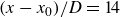
Although self-similarity and mixing characteristics in the steady-state jet have been widely studied (Feikema et al. Reference Feikema, Everest and Driscoll1996; Buch & Dahm Reference Buch and Dahm1998; Su & Clemens Reference Su and Clemens1999; Mi et al. Reference Mi, Nobes and Nathan2001; Karpetis & Barlow Reference Karpetis and Barlow2002; Fuest et al. Reference Fuest, Barlow, Magnotti and Sutton2018; Aparece-Scutariu & Shin Reference Aparece-Scutariu and Shin2022), the stopping jet has received less attention, despite its importance. Borée et al. (Reference Borée, Atassi and Charnay1996) reduced the velocity by half and identified a spatio-temporal similarity behaviour with a time shift. Musculus (Reference Musculus2009) theoretically derived the entrainment wave after which the entrainment increases by three times. Shin et al. (Reference Shin, Aspden, Aparece-Scutariu and Richardson2023) investigated the evolution of the mixture fraction during the decelerating stage, using the same DNS database as for the present study. Both the numerical simulation (see figure 2
a) and a theoretical analysis showed that the mean mixture fraction (
 $\overline {\xi }_c$
) scales with axial distance (
$\overline {\xi }_c$
) scales with axial distance (
 $x$
) and time (
$x$
) and time (
 $t$
) as
$t$
) as
 \begin{equation} \overline {\xi }_c = C_{\xi } \frac {x-x_0}{t-t_0}, \end{equation}
where
 $C_{\xi }$
is a flow-dependent constant, while
$C_{\xi }$
is a flow-dependent constant, while
 $x_0$
and
$x_0$
and
 $t_0$
represent spatial and temporal virtual origins, respectively. Furthermore, second-order statistics (
$t_0$
represent spatial and temporal virtual origins, respectively. Furthermore, second-order statistics (
 $\overline {v ^{\prime}\xi ^{\prime}}$
) also remain self-similar, as shown in figure 2(b), whose radial profile was predicted by a theoretical derivation, assuming self-similarity (see (18) in Shin et al. Reference Shin, Aspden, Aparece-Scutariu and Richardson2023). The assumption of self-similarity allows us to obtain radial profiles, while an integral method does not (Musculus Reference Musculus2009).
$\overline {v ^{\prime}\xi ^{\prime}}$
) also remain self-similar, as shown in figure 2(b), whose radial profile was predicted by a theoretical derivation, assuming self-similarity (see (18) in Shin et al. Reference Shin, Aspden, Aparece-Scutariu and Richardson2023). The assumption of self-similarity allows us to obtain radial profiles, while an integral method does not (Musculus Reference Musculus2009).

Figure 2. (a) Scaled centreline mixture fraction over time, at downstream locations over
 $x/D=7{-}20$
(Shin et al. Reference Shin, Aspden and Richardson2017). (b) Self-similar radial profiles for a stopping jet
$x/D=7{-}20$
(Shin et al. Reference Shin, Aspden and Richardson2017). (b) Self-similar radial profiles for a stopping jet
 $\overline {v ^{\prime}\xi ^{\prime}}$
obtained over
$\overline {v ^{\prime}\xi ^{\prime}}$
obtained over
 $12.5\lt x\lt 20$
and
$12.5\lt x\lt 20$
and
 $50\lt t\lt 69$
(Shin et al. Reference Shin, Aspden, Aparece-Scutariu and Richardson2023), along with centreline slope prediction (see equation (2.10) of Shin et al. Reference Shin, Aspden, Aparece-Scutariu and Richardson2023).
$50\lt t\lt 69$
(Shin et al. Reference Shin, Aspden, Aparece-Scutariu and Richardson2023), along with centreline slope prediction (see equation (2.10) of Shin et al. Reference Shin, Aspden, Aparece-Scutariu and Richardson2023).
This paper aims to characterise the spatial and temporal evolution of the SDR of a stopping jet. First, a theoretical development is made under the assumption of self-similarity. Second, using the DNS dataset, a series of rigorous investigations is conducted to verify self-similarity of the SDR and its directional components. Third, a validation study is conducted to see if the theoretical analysis can predict a transport term. Finally, existing turbulence algebraic models are compared with the DNS dataset, and modifications are proposed.
1.1. Literature review on SDR characteristics and modelling
Experimental SDR measurements in turbulent flows have been the subject of significant efforts. Advancements in optical instrumentation have recently facilitated more accurate three-dimensional measurements. Karpetis & Barlow (Reference Karpetis and Barlow2002) looked at SDR evolution in the case of piloted methane–air jet flames. Geyer et al. (Reference Geyer, Kempf, Dreizler and Janicka2005) performed measurements of SDR in reacting and non-reacting turbulent opposing jets. Kaiser & Frank (Reference Kaiser and Frank2007) obtained two-dimensional images of near-field dissipation structures in hydrogen–methane non-premixed flames. Soulopoulos et al. (Reference Soulopoulos, Hardalupas and Taylor2014, Reference Soulopoulos, Hardalupas and Taylor2015) conducted spatial SDR measurements in non-reactive starting turbulent round jets (figure 3). McManus & Sutton (Reference McManus and Sutton2023) investigated the SDR field in non-premixed turbulent jet flames, focusing on the use of a set of conditional statistics to characterise small-scale structures, including the correlation between dissipation layer widths and temperature, the Reynolds number or dissipation magnitude. Mulla & Hardalupas (Reference Mulla and Hardalupas2022) carried out instantaneous three-dimensional SDR measurements in a turbulent swirling flow, validating the azimuthal component through the assumption of isotropy with the axial component.

Figure 3. Snapshots of instantaneous SDR at different times after the point of starting. The snapshots are taken at non-dimensional times
 $t/T = 3.4, 5, 7.15, 9.65$
from top to bottom and left to right.
$t/T = 3.4, 5, 7.15, 9.65$
from top to bottom and left to right.
Recent progress in computational power has allowed for an examination of turbulent mixing and SDR from a numerical perspective at Reynolds numbers significantly closer to real-world applications than in the past. Still, resolution requirements remain essential, as pointed out by Schumacher et al. (Reference Schumacher, Sreenivasan and Yeung2005) in a DNS investigation of fine scalar mixing. The two main advantages when investigating the SDR numerically are the ability to compute the SDR in every region of the turbulent flow, and the possibility to compute all of the three directional gradients of mixture fraction without any underlying assumptions. Hawkes et al. (Reference Hawkes, Sankaran, Chen, Kaiser and Frank2009) used planar jet flames DNS data to obtain relationships between measured three-dimensional SDR values and lower-dimension estimations. These relationships were beneficial for subsequent experimental efforts targeting the SDR in jet flames (Fuest et al. Reference Fuest, Barlow, Magnotti and Sutton2018; Mulla & Hardalupas Reference Mulla and Hardalupas2022), where measurement of the azimuthal component remained a complex task.
Such SDR modelling has been of continuous interest in the area of turbulent combustion, as it plays an essential role in modelling chemical reaction rates. A robust SDR model should accurately capture turbulent mixing, molecular diffusion and chemical reactions, as well as their interaction. Swaminathan & Bray (Reference Swaminathan and Bray2005) proposed a model for the SDR that includes a chemical time scale besides the scalar–turbulence time scales of the model in (1.1). This was done by analysing the dominant terms of the SDR exact transport equation. The model was validated with DNS data of a premixed flame. Kolla et al. (Reference Kolla, Rogerson, Chakraborty and Swaminathan2009) improved the model of Swaminathan & Bray (Reference Swaminathan and Bray2005) by including the effect of dilatation rate and its influence on scalar–turbulence interaction, chemistry and molecular diffusion. The new model showed good agreement with DNS data over a range of flame conditions. Langella et al. (Reference Langella, Swaminathan, Gao and Chakraborty2015) used the extended algebraic model of Dunstan et al. (Reference Dunstan, Minamoto, Chakraborty and Swaminathan2013), which is based on the work of Kolla et al. (Reference Kolla, Rogerson, Chakraborty and Swaminathan2009), for closure of filtered reaction rate in large eddy simulations (LES) of turbulent piloted methane–air Bunsen flames. The same model of Dunstan et al. (Reference Dunstan, Minamoto, Chakraborty and Swaminathan2013) was used by Langella & Swaminathan (Reference Langella and Swaminathan2016) in unstrained and strained closures for the filtered reaction rate in LES of premixed flames. Comparison with experimental data showed good agreement for the unstrained flamelet closure and an underestimation of the burn rate in the case of the strained flamelet closure.
A transport equation for the SDR was initially derived by Lumley & Khajeh-Nouri (Reference Lumley and Khajeh-Nouri1975) by presuming a close to unity Prandtl number in the context of isotropic turbulence. Lumley (Reference Lumley1976) analysed the equation for a passive scalar in buoyancy driven mixed layers. Later, its applicability was extended to chemically reacting turbulent flows (Borghi Reference Borghi1990; Mantel & Borghi Reference Mantel and Borghi1994; Mura & Borghi Reference Mura and Borghi2003) with constant-density approximations, and also to inhomogeneous turbulence (Jones & Musonge Reference Jones and Musonge1988). Thermal expansion effects due to combustion were included by Swaminathan & Bray (Reference Swaminathan and Bray2005) in the context of premixed flames. Derivation of a
 $\overline {\chi }$
equation is described by Swaminathan & Bray (Reference Swaminathan and Bray2005), with Chakraborty et al. (Reference Chakraborty, Champion, Mura and Swaminathan2011) providing a comprehensive analysis of the SDR budget terms. The same derivation procedure of Swaminathan & Bray (Reference Swaminathan and Bray2005) can be applied for a passive scalar in a constant-density turbulent jet, leading to (3.1).
$\overline {\chi }$
equation is described by Swaminathan & Bray (Reference Swaminathan and Bray2005), with Chakraborty et al. (Reference Chakraborty, Champion, Mura and Swaminathan2011) providing a comprehensive analysis of the SDR budget terms. The same derivation procedure of Swaminathan & Bray (Reference Swaminathan and Bray2005) can be applied for a passive scalar in a constant-density turbulent jet, leading to (3.1).
The mean SDR equation has been of particular interest to the combustion community. Providing reliable models for
 $\overline {\chi }$
in the context of RANS simulations has been the focus of considerable research effort. Tennekes & Lumley (Reference Tennekes and Lumley1972) proposed an order-of-magnitude analysis that indicates that only two of the budget are dominant and scale with the turbulent Reynolds number (3.24). The first relates to scalar–turbulence interaction, representing the tensor scalar product of scalar gradient, and the other accounts for the turbulent strain rate. Using eigenvalue decomposition, the term denoting scalar–turbulence interaction can be written as (Kolla et al. Reference Kolla, Rogerson, Chakraborty and Swaminathan2009)
$\overline {\chi }$
in the context of RANS simulations has been the focus of considerable research effort. Tennekes & Lumley (Reference Tennekes and Lumley1972) proposed an order-of-magnitude analysis that indicates that only two of the budget are dominant and scale with the turbulent Reynolds number (3.24). The first relates to scalar–turbulence interaction, representing the tensor scalar product of scalar gradient, and the other accounts for the turbulent strain rate. Using eigenvalue decomposition, the term denoting scalar–turbulence interaction can be written as (Kolla et al. Reference Kolla, Rogerson, Chakraborty and Swaminathan2009)
 \begin{equation} \text {scalar}{-}\text{turbulence interaction} = -2\,\overline {\chi (e_{\alpha } \cos^2 \alpha + e_{\beta } \cos^2 \beta + e_{\gamma } \cos^2 \gamma )}, \end{equation}
with
 $e_{\alpha }$
,
$e_{\alpha }$
,
 $e_{\beta }$
and
$e_{\beta }$
and
 $e_{\gamma }$
being the turbulent strain tensor
$e_{\gamma }$
being the turbulent strain tensor
 $\partial u^{\prime}_j/\partial x_k$
eigenvalues. The three values satisfy the condition
$\partial u^{\prime}_j/\partial x_k$
eigenvalues. The three values satisfy the condition
 $e_{\alpha } \gt e_{\beta } \gt e_{\gamma }$
, with
$e_{\alpha } \gt e_{\beta } \gt e_{\gamma }$
, with
 $e_{\alpha }$
as the most extensive principal strain rate, and
$e_{\alpha }$
as the most extensive principal strain rate, and
 $e_{\gamma }$
as the most compressive one. Relative orientation of the eigenvector corresponding to the
$e_{\gamma }$
as the most compressive one. Relative orientation of the eigenvector corresponding to the
 $e_{\alpha }$
strain rate is given by
$e_{\alpha }$
strain rate is given by
 $\alpha$
. It follows that the scalar–turbulence interaction acts as a source or sink, depending on predominant alignment of eigenvectors with the scalar gradient. Ashurst et al. (Reference Ashurst, Kerstein, Kerr and Gibson1987) pointed out that in turbulent flows, the scalar gradient has a preference to align with the most compressive principal strain rate, giving this term as a source. As for the other dominant term, which represents the stretching of the scalar field due to its local curvature, this has been related with the characteristic radius of iso-
$\alpha$
. It follows that the scalar–turbulence interaction acts as a source or sink, depending on predominant alignment of eigenvectors with the scalar gradient. Ashurst et al. (Reference Ashurst, Kerstein, Kerr and Gibson1987) pointed out that in turbulent flows, the scalar gradient has a preference to align with the most compressive principal strain rate, giving this term as a source. As for the other dominant term, which represents the stretching of the scalar field due to its local curvature, this has been related with the characteristic radius of iso-
 $\xi$
surfaces (Mantel & Borghi Reference Mantel and Borghi1994).
$\xi$
surfaces (Mantel & Borghi Reference Mantel and Borghi1994).
2. Numerical approach and set-up
The compressible solver HiPSTAR (Sandberg Reference Sandberg2013) is used for the present DNS. HiPSTAR is a highly optimised hybrid MPI/OpenMP solver, used in numerous studies, covering turbulence (Sandberg et al. Reference Sandberg, Sandham and Suponitsky2012; Bechlars & Sandberg Reference Bechlars and Sandberg2017; Shin et al. Reference Shin, Aspden and Richardson2017 ; Saini & Sandberg Reference Saini and Sandberg2020), turbulent mixing (Shin et al. Reference Shin, Sandberg and Richardson2017b ; Zhao & Sandberg Reference Zhao and Sandberg2021) and turbulent flow acoustics (Deuse & Sandberg Reference Deuse and Sandberg2020).
The code uses a structured, multi-block, curvilinear configuration, solving for the governing equations in cylindrical coordinates, thus allowing for an efficient distribution of grid points. Numerical schemes include a fourth-order finite-difference scheme in the streamwise and radial directions, along with a spectral method, based on Fourier decomposition in the azimuthal direction. Coordinate mapping is done in only two dimensions, allowing for a reduced number of metric terms. An axis treatment is applied, using parity conditions (Sandberg Reference Sandberg2011). For improved numerical stability, skew-splitting of convective terms is applied (Kennedy & Gruber Reference Kennedy and Gruber2008). An explicit 11-points filter is applied in all flow directions, with filter weight 0.2, to dampen spurious oscillations (Bogey et al. Reference Bogey, Cacqueray and Bailly2009). An explicit, low-memory, fourth-order, five stages, explicit Runge–Kutta scheme is used for time marching (Kennedy et al. Reference Kennedy, Carpenter and Lewis2000). In addition to the flow governing equations, the conservation equation for a passive scalar is also solved for (see (1) in Aparece-Scutariu & Shin Reference Aparece-Scutariu and Shin2022).
The present DNS consist of a round turbulent air jet, issued into ambient air, without coflow, from a flat plate at Reynolds number
 $Re=7290$
). We define
$Re=7290$
). We define
 $Re = U_0 D/\nu$
, where
$Re = U_0 D/\nu$
, where
 $U_0$
is the inlet velocity,
$U_0$
is the inlet velocity,
 $D$
is the inlet diameter, and
$D$
is the inlet diameter, and
 $\nu$
represents kinematic viscosity. The flow Mach number is subsonic at 0.304. The flow domain is stretched in the axial direction, spanning
$\nu$
represents kinematic viscosity. The flow Mach number is subsonic at 0.304. The flow domain is stretched in the axial direction, spanning
 $55D$
, with
$55D$
, with
 $30D$
in the radial direction. At the jet nozzle, the inflow condition is imposed with a top-hat mean velocity profile and weak turbulent fluctuations using a digital filter (Klein et al. Reference Klein, Sadiki and Janicka2003). A Navier–Stokes non-reflecting characteristic boundary condition (Kim & Lee Reference Kim and Lee2000) is used at the streamwise outflow, with a zonal boundary (Sandberg & Sandham Reference Sandberg and Sandham2006) of 15 points, applied in the outlet vicinity, to dampen any unphysical reflections going back into the domain. In the azimuthal direction, a periodic boundary condition is used. Note that the domain of interest in the present study has length only
$30D$
in the radial direction. At the jet nozzle, the inflow condition is imposed with a top-hat mean velocity profile and weak turbulent fluctuations using a digital filter (Klein et al. Reference Klein, Sadiki and Janicka2003). A Navier–Stokes non-reflecting characteristic boundary condition (Kim & Lee Reference Kim and Lee2000) is used at the streamwise outflow, with a zonal boundary (Sandberg & Sandham Reference Sandberg and Sandham2006) of 15 points, applied in the outlet vicinity, to dampen any unphysical reflections going back into the domain. In the azimuthal direction, a periodic boundary condition is used. Note that the domain of interest in the present study has length only
 $30D$
in the axial direction (figure 4). The remaining
$30D$
in the axial direction (figure 4). The remaining
 $25D$
serves as a safety distance, to reduce the possibility of the outlet exerting an influence on the flow field. The grid independence of the flow solution for the present DNS was previously demonstrated (see figure 1 of Shin et al. Reference Shin, Sandberg and Richardson2017b
), with evidence of well-resolved SDR (see figure 3 of Aparece-Scutariu & Shin Reference Aparece-Scutariu and Shin2022).
$25D$
serves as a safety distance, to reduce the possibility of the outlet exerting an influence on the flow field. The grid independence of the flow solution for the present DNS was previously demonstrated (see figure 1 of Shin et al. Reference Shin, Sandberg and Richardson2017b
), with evidence of well-resolved SDR (see figure 3 of Aparece-Scutariu & Shin Reference Aparece-Scutariu and Shin2022).
Initially, the simulation runs from the quiescent flow field until a statistically stationary flow is established. Stationarity is demonstrated by the evolution of flow quantities, as shown by Shin et al. (Reference Shin, Sandberg and Richardson2017b
) and Aparece-Scutariu & Shin (Reference Aparece-Scutariu and Shin2022). Then the inlet velocity is suddenly set to zero, resetting the time to
 $t=0$
. From the stopping point, one realisation is simulated until
$t=0$
. From the stopping point, one realisation is simulated until
 $t=69\tau$
, where
$t=69\tau$
, where
 $\tau$
is the characteristic jet time, defined as
$\tau$
is the characteristic jet time, defined as
 $\tau =D/U_0$
. Note that 10 statistically independent realisations are produced for ensemble averaging. Due to the limited number of only 10 stopping jet instances, data were filtered for any noise using a one-dimensional Savitzky–Golay filter, based on local second-order polynomial fits over sets of points with fixed width (Guest Reference Guest2012). Figure 4(a–d) show the instantaneous non-dimensional SDR field from one realisation, at different times after the point of stopping (
$\tau =D/U_0$
. Note that 10 statistically independent realisations are produced for ensemble averaging. Due to the limited number of only 10 stopping jet instances, data were filtered for any noise using a one-dimensional Savitzky–Golay filter, based on local second-order polynomial fits over sets of points with fixed width (Guest Reference Guest2012). Figure 4(a–d) show the instantaneous non-dimensional SDR field from one realisation, at different times after the point of stopping (
 $t/\tau =0$
).
$t/\tau =0$
).

Figure 4. Non-dimensional instantaneous SDR in (a) the steady-state jet, and the stopping jet at times after stopping (b)
 $10\tau$
, (c)
$10\tau$
, (c)
 $25\tau$
, (d)
$25\tau$
, (d)
 $50\tau$
.
$50\tau$
.
3. Results
This section is structured as follows. First, a theoretical analysis assuming self-similarity is presented. The theoretical analysis provides relationships between self-similar variables, including an explicit relationship for
 $\overline {v ^{\prime} \chi^{\prime}}$
, which serves as a validation of the theoretical development. Subsequently, self-similarity characteristics of the stopping jet are presented through subsections covering evolution of the centreline profiles, radial profiles of individual terms of the transport equation, and the budget terms. Then the radial profile of
$\overline {v ^{\prime} \chi^{\prime}}$
, which serves as a validation of the theoretical development. Subsequently, self-similarity characteristics of the stopping jet are presented through subsections covering evolution of the centreline profiles, radial profiles of individual terms of the transport equation, and the budget terms. Then the radial profile of
 $\overline {v ^{\prime} \chi^{\prime}}$
is compared against the derived relationship in the theoretical subsection. Finally, existing algebraic models of the SDR-related terms are compared with DNS data, proposing suitable model coefficients and modifications.
$\overline {v ^{\prime} \chi^{\prime}}$
is compared against the derived relationship in the theoretical subsection. Finally, existing algebraic models of the SDR-related terms are compared with DNS data, proposing suitable model coefficients and modifications.
3.1. Theoretical analysis assuming self-similarity
In this subsection, a theoretical analysis on the mean SDR is developed, using the assumption that flow variables remain self-similar in the unsteady jet. The assumptions of self-similarity will be thoroughly checked by DNS data in §§ 3.3 and 3.4. Furthermore, obtained theoretical predictions will be validated in § 3.5.
The analysis starts from the transport equation for the mean SDR in the case of an incompressible jet with constant mass diffusivity
 $\mathscr {D}$
:
$\mathscr {D}$
:
 \begin{equation} \begin{gathered} \frac {\partial \,\overline {\chi }}{\partial t} + \frac {\partial \overline {u_j}\,\, \overline {\chi }}{\partial x_j} = \mathscr {D} \frac {\partial ^2 \overline {\chi }}{\partial x_j \partial x_j} -\frac {\partial \overline {u^{\prime}_j \chi^{\prime}}}{\partial x_j} -4 \mathscr {D} \overline {\frac {\partial \xi }{\partial x_j} \frac {\partial u_j}{\partial x_i} \frac {\partial \xi }{\partial x_i}} -4 \mathscr {D}^2 \overline {\frac {\partial ^2 \xi }{\partial x_j \partial x_i}\frac {\partial ^2 \xi }{\partial x_j \partial x_i}}. \end{gathered} \end{equation}
Next, assuming that all involved variables are self-similar, the scaled ensemble-averaged statistics can be represented by a scaled radius
 $\eta =r/(x-x_0)$
, where
$\eta =r/(x-x_0)$
, where
 $x_0$
represents the jet virtual origin. Flow variables can be normalised by centreline values as
$x_0$
represents the jet virtual origin. Flow variables can be normalised by centreline values as
 \begin{equation} \begin{gathered} \overline {\chi } = \overline {\chi }_c g_{\chi }(\eta ),\quad\overline {u} = \overline {u}_c g_u(\eta ),\quad\overline {v} = \overline {u}_c g_v(\eta ), \\[5pt] \overline {u^{\prime}\chi^{\prime}} = \overline {u}_c\,\overline {\chi }_c\, g_{u^{\prime}\chi^{\prime}}(\eta ),\quad\overline {v ^{\prime}\chi^{\prime}} = \overline {u}_c\,\overline {\chi }_c\, g_{v ^{\prime}\chi^{\prime}}(\eta ), \\[5pt] 4 \mathscr {D}^2\, \overline {\frac {\partial ^2 \xi }{\partial x_j\, \partial x_k}\frac {\partial ^2 \xi }{\partial x_j\, \partial x_k}} =\frac {\overline {u}_c\, \overline {\chi }_c}{r_{1/2}} h(\eta ), \\[5pt] 4 \mathscr {D}\, \overline {\frac {\partial \xi }{\partial x_j} \frac {\partial u_j}{\partial x_k} \frac {\partial \xi }{\partial x_k}} = \frac {\overline {u}_c\, \overline {\chi }_c}{r_{1/2}} l(\eta ), \end{gathered} \end{equation}
where
 $g_\chi$
,
$g_\chi$
,
 $g_u$
,
$g_u$
,
 $g_v$
,
$g_v$
,
 $g_{u^{\prime}\chi^{\prime}}$
,
$g_{u^{\prime}\chi^{\prime}}$
,
 $g_{v ^{\prime}\chi^{\prime}}$
,
$g_{v ^{\prime}\chi^{\prime}}$
,
 $h$
and
$h$
and
 $l$
are dimensionless shape functions characterising the self-similar profiles, respectively. Note that
$l$
are dimensionless shape functions characterising the self-similar profiles, respectively. Note that
 $r_{1/2}$
is the so-called half-radius, i.e. the radial location where axial velocity is half of the centreline axial velocity. Centreline variables
$r_{1/2}$
is the so-called half-radius, i.e. the radial location where axial velocity is half of the centreline axial velocity. Centreline variables
 $\overline {u}_c$
and
$\overline {u}_c$
and
 $\overline {\chi }_c$
are functions of
$\overline {\chi }_c$
are functions of
 $\eta$
and
$\eta$
and
 $t$
. In previous studies of the stopping jet,
$t$
. In previous studies of the stopping jet,
 $\overline {u}_c$
and
$\overline {u}_c$
and
 $r_{1/2}$
are characterised as (Shin et al. Reference Shin, Aspden and Richardson2017; Pope Reference Pope2000)
$r_{1/2}$
are characterised as (Shin et al. Reference Shin, Aspden and Richardson2017; Pope Reference Pope2000)
 \begin{align} \overline {u}_c &= C_u \frac {x-x_0}{t-t_0}, \notag\\ r_{1/2} &= S (x-x_0), \end{align}
where
 $t_0$
is a time shift, and
$t_0$
is a time shift, and
 $C_u$
and
$C_u$
and
 $S$
are some constants.
$S$
are some constants.
Substituting the relations in (3.2) and (3.3) into (3.1) results in
 \begin{align} \frac {g_{\chi }}{C_u}\frac {t-t_0}{\overline {\chi }_c} \frac {\partial \overline {\chi }_c}{\partial t} + \left(g_u g_{\chi } + g_{u^{\prime}\chi^{\prime}}\right) \frac {x-x_0}{\overline {\chi }_c} \frac {\partial \overline {\chi }_c}{\partial x}&= \eta g_u \frac {{\rm d} g_{\chi }}{{\rm d} \eta }-g_v\frac {{\rm d} g_{\chi }}{{\rm d} \eta }-\frac {1}{\eta } \frac {{\rm d}\left(\eta g_{v ^{\prime}\chi^{\prime}}\right)}{{\rm d}\eta }\nonumber \\ &\quad +\eta \frac {{\rm d} g_{u^{\prime}\chi^{\prime}}}{{\rm d} \eta }-g_{u^{\prime}\chi^{\prime}}-\frac {1}{S}(h+l). \end{align}
The terms on the right-hand side of (3.4) are functions of
 $\eta$
only, while the terms on the left-hand side are functions of
$\eta$
only, while the terms on the left-hand side are functions of
 $x$
and
$x$
and
 $t$
. In order for equality to hold,
$t$
. In order for equality to hold,
 $\overline {\chi }_c$
only accepts a power-law form as
$\overline {\chi }_c$
only accepts a power-law form as
 \begin{equation} \overline {\chi }_c(x,t) = C_X (x-x_0)^a (t-t_0)^b, \end{equation}
where
 $C_X$
is a constant. The power-law exponents
$C_X$
is a constant. The power-law exponents
 $a$
and
$a$
and
 $b$
cannot be determined any further in this analysis. In Shin et al. (Reference Shin, Aspden and Richardson2017), power-law exponents of
$b$
cannot be determined any further in this analysis. In Shin et al. (Reference Shin, Aspden and Richardson2017), power-law exponents of
 $\overline {u}_c$
for a stopping jet were determined explicitly using a similar approach. However, the difference is that velocity is nonlinear in its governing equation (momentum equation), while
$\overline {u}_c$
for a stopping jet were determined explicitly using a similar approach. However, the difference is that velocity is nonlinear in its governing equation (momentum equation), while
 $\overline {\chi }$
is linear in its governing equation (see (3.1)).
$\overline {\chi }$
is linear in its governing equation (see (3.1)).
It will be shown in § 3.2 that present DNS data indicate
 $a=1$
and
$a=1$
and
 $b=-2$
as a good fit for
$b=-2$
as a good fit for
 $\overline {\chi }_c$
evolution, giving
$\overline {\chi }_c$
evolution, giving
 \begin{equation} \overline {\chi }_c(x,t) = \frac {C_{\overline {\chi }_c}}{U_0} \frac {x-x_0}{(t-t_0)^{2}}, \end{equation}
where a division by
 $U_0$
is included to match dimensions. Then substitution of (3.6) into (3.4) gives
$U_0$
is included to match dimensions. Then substitution of (3.6) into (3.4) gives
 \begin{align} -\frac {2}{C_u} g_{\chi } + g_u g_{\chi } - \eta g_u \frac {{\rm d} g_{\chi }}{{\rm d} \eta } + g_v \frac {{\rm d} g_{\chi }}{{\rm d} \eta } &= - \left [ \frac {g_{v^{\prime }\chi ^{\prime }}}{\eta } + \frac {{\rm d} g_{v^{\prime }\chi ^{\prime }}}{{\rm d} \eta } \right ] - \left [ 2 g_{u^{\prime }\chi ^{\prime }} - \eta \frac {{\rm d} g_{u^{\prime }\chi ^{\prime }}}{{\rm d} \eta } \right ] \nonumber \\ &\quad - \frac {1}{S}(h+l). \end{align}
Note that
 $C_{\overline {\chi }_c}$
does not appear in (3.7), due to linear dependency of
$C_{\overline {\chi }_c}$
does not appear in (3.7), due to linear dependency of
 $\overline {\chi }$
in the SDR transport equation (see (3.1)). At
$\overline {\chi }$
in the SDR transport equation (see (3.1)). At
 $\eta =0$
, the following relationships hold due to definitions and symmetry:
$\eta =0$
, the following relationships hold due to definitions and symmetry:
 \begin{align} g_u(0) = 1, \quad g_v(0) = 0, \quad g_{\chi }(0) = 1, \quad g_{v ^{\prime} \chi^{\prime}} = 0. \end{align}
With the above relationships, evaluating (3.7) at
 $\eta =0$
gives
$\eta =0$
gives
 \begin{equation} \left [\frac {{\rm d} g_{v ^{\prime}\chi^{\prime}}}{{\rm d}\eta } \right ]_{\eta =0} = \frac {1}{C_u} - \frac {1}{2} - g_{u^{\prime}\chi^{\prime}}(0) - \frac {1}{2S}\big [h(0)+l(0)\big ]. \end{equation}
Next, (3.7) can be integrated to obtain an explicit expression for
 $g_{v^{\prime }\chi ^{\prime }}$
as
$g_{v^{\prime }\chi ^{\prime }}$
as
 \begin{align} g_{v^{\prime }\chi ^{\prime }}={}&\frac {2}{\eta C_u} \int _{0}^\eta \eta ^{\prime } g_{\chi }\, {\rm d}\eta ^{\prime } - \frac {4}{\eta } \int _{0}^\eta \eta ^{\prime } g_u g_{\chi }\, {\rm d}\eta ^{\prime } + \frac {3 g_{\chi }}{\eta } \int _{0}^\eta \eta ^{\prime } g_u\, {\rm d}\eta ^{\prime }\nonumber \\ &{}+ \eta g_{u^{\prime }{\chi }^{\prime }}-\frac {4}{\eta } \int _{0}^\eta \eta ^{\prime } g_{u^{\prime }{\chi }^{\prime }}\, {\rm d}\eta ^{\prime } - \frac {1}{\eta S} \int _{0}^\eta \eta ^{\prime } (h+l)\, {\rm d}\eta ^{\prime }. \end{align}
The two explicit expressions of (3.9) and (3.10) are compared with simulation data in § 3.5.
3.2. Centreline SDR
In this subsection, centreline SDR (
 $\overline {\chi }_c$
) of the stopping jet is characterised using DNS. As shown in (3.2), centreline characteristics are the starting point of the self-similar analysis. The theoretical analysis in § 3.1 has not reached a conclusion on spatial and temporal dependencies. This will be solved in this subsection (see the paragraph after (3.5)).
$\overline {\chi }_c$
) of the stopping jet is characterised using DNS. As shown in (3.2), centreline characteristics are the starting point of the self-similar analysis. The theoretical analysis in § 3.1 has not reached a conclusion on spatial and temporal dependencies. This will be solved in this subsection (see the paragraph after (3.5)).

Figure 5. Centreline SDR variation with axial distance at multiple time instances.
Figure 5 shows the spatial and temporal evolution of
 $\overline {\chi }_c$
after stopping. Thin coloured lines represent ensemble-averaged
$\overline {\chi }_c$
after stopping. Thin coloured lines represent ensemble-averaged
 $\overline {\chi }_c$
– note that ensemble averaging was done over 10 realisations. Profiles are normalised by the characteristic jet time
$\overline {\chi }_c$
– note that ensemble averaging was done over 10 realisations. Profiles are normalised by the characteristic jet time
 $\tau = D/U_0$
, with
$\tau = D/U_0$
, with
 $D$
and
$D$
and
 $U_0$
as the source diameter and velocity, respectively. The jet virtual origin
$U_0$
as the source diameter and velocity, respectively. The jet virtual origin
 $x_0 = 2.39D$
remains the same as for the steady-state jet (Shin et al. Reference Shin, Sandberg and Richardson2017b
). For reference, the steady-state
$x_0 = 2.39D$
remains the same as for the steady-state jet (Shin et al. Reference Shin, Sandberg and Richardson2017b
). For reference, the steady-state
 $\overline {\chi }_c$
is added as a thick black line. Overall,
$\overline {\chi }_c$
is added as a thick black line. Overall,
 $\overline {\chi }_c$
decreases from its steady-state profile after stopping.
$\overline {\chi }_c$
decreases from its steady-state profile after stopping.
In the inlet vicinity (
 $x/D \approx 0$
), centreline SDR momentarily increases immediately after stopping, then slowly decreases again to zero. The region corresponds to the potential core so that
$x/D \approx 0$
), centreline SDR momentarily increases immediately after stopping, then slowly decreases again to zero. The region corresponds to the potential core so that
 $\overline {\chi }_c$
is zero in the steady-state jet (see figure 4
a). After the jet is stopped, the potential core collapses inwards, and SDR in the nozzle vicinity is no longer zero (see figure 4
b). As time advances, SDR approaches to zero, as seen in figure 4(c,d).
$\overline {\chi }_c$
is zero in the steady-state jet (see figure 4
a). After the jet is stopped, the potential core collapses inwards, and SDR in the nozzle vicinity is no longer zero (see figure 4
b). As time advances, SDR approaches to zero, as seen in figure 4(c,d).
Further downstream, after a peak,
 $\overline {\chi }_c$
evolves in the same way as for the steady-state profile. Behaviour is also similar to the observations of decelerating diesel jets (Musculus Reference Musculus2009). After stopping, the decelerating wave propagates downstream with a certain speed. At locations where the decelerating wave has not arrived,
$\overline {\chi }_c$
evolves in the same way as for the steady-state profile. Behaviour is also similar to the observations of decelerating diesel jets (Musculus Reference Musculus2009). After stopping, the decelerating wave propagates downstream with a certain speed. At locations where the decelerating wave has not arrived,
 $\overline {\chi }_c$
remains the same as in the steady-state jet. Similarity with the steady-state profile can also be seen in the instantaneous images of figure 4 – the instantaneous SDR characteristics after
$\overline {\chi }_c$
remains the same as in the steady-state jet. Similarity with the steady-state profile can also be seen in the instantaneous images of figure 4 – the instantaneous SDR characteristics after
 $x/D\gt 25$
remain similar for
$x/D\gt 25$
remain similar for
 $t/\tau = 0{-}50$
.
$t/\tau = 0{-}50$
.

Figure 6. (a) The parabolic regime and (b) the inverse of
 $\overline {\chi }_c$
slope behaviour near the nozzle.
$\overline {\chi }_c$
slope behaviour near the nozzle.
Long-term behaviour of the intermediate region between the nozzle inlet and the peak of
 $\overline {\chi }_c$
(e.g.
$\overline {\chi }_c$
(e.g.
 $1\lt (x-x_0)/D\lt 7$
at
$1\lt (x-x_0)/D\lt 7$
at
 $t/\tau = 5$
) will be analysed further.
$t/\tau = 5$
) will be analysed further.
Figures 6(a) and 6(b) replotted centreline SDR in two different ways to investigate spatial and temporal dependencies on the intermediate region. Figure 6(a) shows
 $\overline {\chi }_c$
in the log-log scale, with the
$\overline {\chi }_c$
in the log-log scale, with the
 $x$
-axis being the axial distance with
$x$
-axis being the axial distance with
 $1\lt (x-x_0)/D\lt 12$
. For reference,
$1\lt (x-x_0)/D\lt 12$
. For reference,
 $y=x$
is added as a thick black line. As time advances,
$y=x$
is added as a thick black line. As time advances,
 $\overline {\chi }_c$
becomes parallel to the black line, indicating that
$\overline {\chi }_c$
becomes parallel to the black line, indicating that
 $\overline {\chi }_c$
becomes linear in
$\overline {\chi }_c$
becomes linear in
 $x$
. Similarly, figure 6(b) shows
$x$
. Similarly, figure 6(b) shows
 $\overline {\chi }_c$
in the log-log scale with the
$\overline {\chi }_c$
in the log-log scale with the
 $x$
-axis being the time with
$x$
-axis being the time with
 $5\lt (t-\tau _0)/\tau \lt 56$
. For reference,
$5\lt (t-\tau _0)/\tau \lt 56$
. For reference,
 $y=x^{-1}$
and
$y=x^{-1}$
and
 $y=x^{-2}$
are added as thick blue and black lines. In the long time and in the far field,
$y=x^{-2}$
are added as thick blue and black lines. In the long time and in the far field,
 $\overline {\chi }_c$
becomes parallel to the black line, meaning that
$\overline {\chi }_c$
becomes parallel to the black line, meaning that
 $\overline {\chi }_c$
asymptotes to a
$\overline {\chi }_c$
asymptotes to a
 $[(t-t_0)/\tau ]^{-2}$
dependency. The analysis indicates that exponents in (3.5) are
$[(t-t_0)/\tau ]^{-2}$
dependency. The analysis indicates that exponents in (3.5) are
 $a=1$
and
$a=1$
and
 $b=-2$
, respectively. The long term behaviour of
$b=-2$
, respectively. The long term behaviour of
 $\overline {\chi }_c$
in the intermediate regime can be expressed as
$\overline {\chi }_c$
in the intermediate regime can be expressed as
 \begin{equation} \overline {\chi }_c = \frac {C_{\overline {\chi }_c}}{U_0} \frac {x-x_0}{(t - t_0)^2}, \end{equation}
where
 $C_{\overline {\chi }_c}$
is a dimensionless coefficient whose value will be evaluated, and
$C_{\overline {\chi }_c}$
is a dimensionless coefficient whose value will be evaluated, and
 $U_0$
is included to match the dimension.
$U_0$
is included to match the dimension.

Figure 7. Scaled centreline SDR with time and axial distance at different axial locations.

Figure 8. (a) False colours of
 $\overline {\chi }_c U_0 (t - t_0)^2/(x - x_0)$
, and (b) deceleration wave speed (
$\overline {\chi }_c U_0 (t - t_0)^2/(x - x_0)$
, and (b) deceleration wave speed (
 $\overline {u}_{wave}$
) for
$\overline {u}_{wave}$
) for
 $\overline {\chi }_c$
, along with evolution of centreline axial velocity
$\overline {\chi }_c$
, along with evolution of centreline axial velocity
 $\overline {u}_c$
.
$\overline {u}_c$
.
Figure 7 shows scaled
 $\overline {\chi }_c$
over time to reconfirm spatial and temporal dependencies – the centreline SDR is scaled by
$\overline {\chi }_c$
over time to reconfirm spatial and temporal dependencies – the centreline SDR is scaled by
 $(x - x_0)/U_0(t - t_0)^2$
. Again, the scaled
$(x - x_0)/U_0(t - t_0)^2$
. Again, the scaled
 $\overline {\chi }_c$
asymptotes to a constant in the long term. Scatter around the asymptotic value remains low, compared to the magnitude of early (
$\overline {\chi }_c$
asymptotes to a constant in the long term. Scatter around the asymptotic value remains low, compared to the magnitude of early (
 $t/\tau \lt 14$
) scaled profiles. The asymptotic constant
$t/\tau \lt 14$
) scaled profiles. The asymptotic constant
 $C_{\overline {\chi }_c}$
is
$C_{\overline {\chi }_c}$
is
 $0.00105$
, as shown by the dashed line.
$0.00105$
, as shown by the dashed line.
Next, the decelerating wave for the SDR is analysed. To quantify the decelerating wave, figure 8(a) shows the false colour of
 $ \overline {\chi }_cU_0 (t - t_0)^2/(x - x_0)$
, using log scales. The false colour displays a boundary separating two regions, one in red and the other in white. The boundary is not distinctive, but rather smooth with some width. Still, the boundary is clearly parallel to
$ \overline {\chi }_cU_0 (t - t_0)^2/(x - x_0)$
, using log scales. The false colour displays a boundary separating two regions, one in red and the other in white. The boundary is not distinctive, but rather smooth with some width. Still, the boundary is clearly parallel to
 $y=x^2$
. Hence this is treated as a characteristic line and drawn on the figure with a functional form as
$y=x^2$
. Hence this is treated as a characteristic line and drawn on the figure with a functional form as
 \begin{equation} \frac {t-t_0}{\tau } = \frac {1}{2C_{wave,SDR}} \left ( \frac {x-x_0}{D} \right )^2. \end{equation}
As the boundary is not very distinctive, three candidates for
 $1/(2C_{wave,SDR})$
are selected, representing high, medium and low bounds with values
$1/(2C_{wave,SDR})$
are selected, representing high, medium and low bounds with values
 $0.061$
,
$0.061$
,
 $0.053$
and
$0.053$
and
 $0.046$
, respectively. Hence
$0.046$
, respectively. Hence
 $C_{wave,SDR}$
takes values 8.2, 9.43 and 10.87, respectively. By the method of characteristics, the characteristic line in (3.12) should be a solution of the characteristic equation
$C_{wave,SDR}$
takes values 8.2, 9.43 and 10.87, respectively. By the method of characteristics, the characteristic line in (3.12) should be a solution of the characteristic equation
 \begin{equation} \frac {{\rm d}x}{{\rm d}t} = u_{wave,SDR}. \end{equation}
With (3.12),
 $u_{wave,SDR}$
satisfies
$u_{wave,SDR}$
satisfies
 \begin{equation} \frac {u_{wave,SDR}}{U_0} = \frac {C_{wave,SDR}}{(x-x_0)/D}. \end{equation}
The
 $1/x$
dependency of
$1/x$
dependency of
 $u_{wave,SDR}$
indicates that the SDR deceleration wave has a behaviour similar to that of the deceleration wave for axial velocity (
$u_{wave,SDR}$
indicates that the SDR deceleration wave has a behaviour similar to that of the deceleration wave for axial velocity (
 $\overline {u}_c$
) in the stopping jet (Shin et al. Reference Shin, Aspden and Richardson2017), which is
$\overline {u}_c$
) in the stopping jet (Shin et al. Reference Shin, Aspden and Richardson2017), which is
 \begin{equation} \frac {u_{wave,velocity}}{U_0} = \frac {7.71}{(x-x_0)/D}. \end{equation}
For comparison, figure 8(b) shows the decelerating wave speeds for centreline SDR and axial velocity. This indicates that overall, the deceleration wave speed for SDR is slightly higher than for axial velocity. A quantitative comparison between the SDR wave speed and centreline axial velocity indicates that the former is between 1.06 and 1.41 times higher for the high and low bounds in figure 8(b), respectively.
Figure 8(a) can also be used to set the ranges, where the long-term asymptotic behaviour is observed. The horizontal black dashed line is the line
 $(t-\tau _0)/\tau =36$
, which crosses the decelerating wave line (black solid line) at
$(t-\tau _0)/\tau =36$
, which crosses the decelerating wave line (black solid line) at
 $(x-x_0)/D=26$
. Considering
$(x-x_0)/D=26$
. Considering
 $x_0=2.39D$
and
$x_0=2.39D$
and
 $t_0=14\tau$
, the ranges
$t_0=14\tau$
, the ranges
 $14\lt x/D\lt 28$
and
$14\lt x/D\lt 28$
and
 $50\lt t/\tau \lt 69$
can be used to obtain statistics for long-term behaviour analysis.
$50\lt t/\tau \lt 69$
can be used to obtain statistics for long-term behaviour analysis.
3.3. Self-similarity of the mean SDR in a stopping jet
This subsection analyses radial profiles of the mean SDR and its axial, radial and azimuthal components. As shown in § 3.2, scaled centreline SDR
 $ \overline {\chi }_c U_0 (t - t_0)^2/(x - x_0)$
asymptotes to a constant value, after some transient time. Based on this behaviour, the current subsection focuses on identifying new self-similar states in the stopping jet. In the first subsubsection, stationarity and homogeneity of normalised radial profiles of the SDR are investigated. The second subsubsection presents new self-similar states, which are different from their steady-state counterparts.
$ \overline {\chi }_c U_0 (t - t_0)^2/(x - x_0)$
asymptotes to a constant value, after some transient time. Based on this behaviour, the current subsection focuses on identifying new self-similar states in the stopping jet. In the first subsubsection, stationarity and homogeneity of normalised radial profiles of the SDR are investigated. The second subsubsection presents new self-similar states, which are different from their steady-state counterparts.
3.3.1. Stationarity and homogeneity of the SDR radial profiles
Stationarity of SDR and its components is first checked at selected axial locations
 $(x-x_0)/D = 14$
and
$(x-x_0)/D = 14$
and
 $28$
. Figure 9 shows radial profiles of axial, radial, azimuthal and the total SDR components, at different times after the jet is stopped. Profiles are normalised by centreline SDR (
$28$
. Figure 9 shows radial profiles of axial, radial, azimuthal and the total SDR components, at different times after the jet is stopped. Profiles are normalised by centreline SDR (
 $\overline {\chi }_c$
). On each plot, the blue thick line represents averaged profile over
$\overline {\chi }_c$
). On each plot, the blue thick line represents averaged profile over
 $t/\tau = 50{-}69$
to be termed hereafter ‘long-term profiles’. As seen in figure 8(a), the decelerating wave passes by at approximately
$t/\tau = 50{-}69$
to be termed hereafter ‘long-term profiles’. As seen in figure 8(a), the decelerating wave passes by at approximately
 $t/\tau = 24$
and
$t/\tau = 24$
and
 $35$
for
$35$
for
 $(x-x_0)/D=14$
and
$(x-x_0)/D=14$
and
 $28$
, respectively. Hence the time range
$28$
, respectively. Hence the time range
 $t/\tau = 50{-}69$
falls into the interval where long-term behaviour can be observed at both locations.
$t/\tau = 50{-}69$
falls into the interval where long-term behaviour can be observed at both locations.

Figure 9. Normalised radial profiles of transient axial SDR component at (a)
 $(x-x_0)/D = 14$
and (e)
$(x-x_0)/D = 14$
and (e)
 $(x-x_0)/D = 28$
, radial SDR component at (b)
$(x-x_0)/D = 28$
, radial SDR component at (b)
 $(x-x_0)/D = 14$
and (f)
$(x-x_0)/D = 14$
and (f)
 $(x-x_0)/D=28$
, azimuthal SDR component at (c)
$(x-x_0)/D=28$
, azimuthal SDR component at (c)
 $(x-x_0)/D = 14$
and (g)
$(x-x_0)/D = 14$
and (g)
 $(x-x_0)/D = 28$
, total SDR at (d)
$(x-x_0)/D = 28$
, total SDR at (d)
 $(x-x_0)/D = 14$
and (h)
$(x-x_0)/D = 14$
and (h)
 $(x-x_0)/D = 28$
.
$(x-x_0)/D = 28$
.
Overall, transient profiles increase over time. As time advances, profiles start near the steady-state profiles (black lines), and slowly move to long-term profiles (blue lines), then settle down at the long-term profiles.
Figures 9(a) and 9(e) show the normalised axial SDR components. The long-term profiles are higher than their steady-state counterparts. At both axial locations, long-term profiles slightly increase with
 $\eta$
, from the centreline towards a peak, and then decay to zero further away from the centreline. Figures 9(b) and 9( f) show the normalised radial SDR components. The long-term profiles show the highest increase in magnitude, compared to the steady-state profiles. The increase is mostly visible at
$\eta$
, from the centreline towards a peak, and then decay to zero further away from the centreline. Figures 9(b) and 9( f) show the normalised radial SDR components. The long-term profiles show the highest increase in magnitude, compared to the steady-state profiles. The increase is mostly visible at
 $(x-x_0)/D=28$
, which also shows the highest peak dissipation at
$(x-x_0)/D=28$
, which also shows the highest peak dissipation at
 $\eta \approx 0.09$
, approximately 2.5 times higher than the centreline value. Figures 9(c) and 9(g) show the azimuthal SDR component. Long-term profiles resemble those of the axial component, which is also the case for the steady-state jet. At
$\eta \approx 0.09$
, approximately 2.5 times higher than the centreline value. Figures 9(c) and 9(g) show the azimuthal SDR component. Long-term profiles resemble those of the axial component, which is also the case for the steady-state jet. At
 $(x-x_0)/D=14$
, the long-term profile is relatively flat, whereas at
$(x-x_0)/D=14$
, the long-term profile is relatively flat, whereas at
 $(x-x_0)/D=28$
, there is a distinct peak in dissipation at
$(x-x_0)/D=28$
, there is a distinct peak in dissipation at
 $\eta \approx 0.07$
.
$\eta \approx 0.07$
.
Finally, figures 9(d) and 9(h) show the total SDR long-term profiles. Again, the long-term profiles are higher than the steady-state profiles, with the largest contribution from the radial component. Also, on all figures, the instantaneous profiles of
 $t/\tau =50, 60, 69$
are all around the long-term profiles, which confirms stationarity in the inspected time range. Furthermore, total SDR goes to zero at the same
$t/\tau =50, 60, 69$
are all around the long-term profiles, which confirms stationarity in the inspected time range. Furthermore, total SDR goes to zero at the same
 $\eta$
location for both steady-state and long-term profiles. This indicates that the jet spreading angle does not change while the jet is decelerating.
$\eta$
location for both steady-state and long-term profiles. This indicates that the jet spreading angle does not change while the jet is decelerating.

Figure 10. Temporally averaged profiles of normalised SDR components (a) axial, (b) radial and (c) azimuthal as well as (d) total SDR at
 $(x-x_0)/D = 14{-}28$
; and self-similar profiles averaged over
$(x-x_0)/D = 14{-}28$
; and self-similar profiles averaged over
 $t/\tau = 50{-}69$
and
$t/\tau = 50{-}69$
and
 $(x-x_0)/D = 14{-}28$
for SDR components (e) axial, (f) radial and (g) azimuthal as well as (h) total SDR.
$(x-x_0)/D = 14{-}28$
for SDR components (e) axial, (f) radial and (g) azimuthal as well as (h) total SDR.
3.3.2. Homogeneity of the SDR radial profiles
Next, homogeneity of profiles is investigated. Figures 10(a–d) show long-term radial profiles (i.e. averaged over
 $t/\tau = 50{-}69$
) of the SDR and its components at axial locations
$t/\tau = 50{-}69$
) of the SDR and its components at axial locations
 $(x-x_0)/D = 14{-}28$
. At each axial location of the given range, stationarity is observed at the inspected times, as shown in figure 9. Overall, there is some degree of scatter among the lines in all figures. The scatter would be attributed to limited simulation data – the ensemble averaging uses 10 azimuthally averaged realisations. Still, the small scatter indicates that long-term profiles are homogeneous after the passage of the decelerating wave.
$(x-x_0)/D = 14{-}28$
. At each axial location of the given range, stationarity is observed at the inspected times, as shown in figure 9. Overall, there is some degree of scatter among the lines in all figures. The scatter would be attributed to limited simulation data – the ensemble averaging uses 10 azimuthally averaged realisations. Still, the small scatter indicates that long-term profiles are homogeneous after the passage of the decelerating wave.
Among the SDR components, overall shapes and magnitudes are similar to each other. Similarity indicates that the mean SDR is isotropic, hence the total SDR can be inferred from one component of the SDR. The
 $\overline {\chi }/\overline {\chi }_c$
radial profile increases approximately 1.5 times the centreline value, until
$\overline {\chi }/\overline {\chi }_c$
radial profile increases approximately 1.5 times the centreline value, until
 $\eta \approx 0.1$
, followed by a decay to zero until
$\eta \approx 0.1$
, followed by a decay to zero until
 $\eta =0.25$
.
$\eta =0.25$
.
So far, stationarity and homogeneity were evaluated for the time interval
 $t/\tau = 50{-}69$
and over the axial distance
$t/\tau = 50{-}69$
and over the axial distance
 $(x-x_0)/D = 14{-}28$
. The choices of the ranges for
$(x-x_0)/D = 14{-}28$
. The choices of the ranges for
 $x$
and
$x$
and
 $t$
are imposed by nozzle proximity, available simulation time and speed of the deceleration wave. The ranges fall inside the regime in which the centreline SDR reaches an asymptotic state (figure 6). Hence chosen ranges of
$t$
are imposed by nozzle proximity, available simulation time and speed of the deceleration wave. The ranges fall inside the regime in which the centreline SDR reaches an asymptotic state (figure 6). Hence chosen ranges of
 $x$
and
$x$
and
 $t$
intervals are wide enough to highlight universality of radial profiles, with a ratio for axial locations calculated based on
$t$
intervals are wide enough to highlight universality of radial profiles, with a ratio for axial locations calculated based on
 $x - x_0=15$
and time span
$x - x_0=15$
and time span
 $19\tau$
.
$19\tau$
.
Figures 10(e–h) show spatially averaged long-term profiles of the total SDR and its three components, to be termed hereafter ‘decelerating self-similar profiles’. Decelerating self-similar profiles in the blue thick lines are obtained by averaging the long-term profiles over
 $t/\tau = 50{-}69$
and
$t/\tau = 50{-}69$
and
 $(x-x_0)/D = 14{-}28$
. Black thick lines are the steady-state self-similar profiles. The shaded region represents an error bound of one standard deviation (S.D.).
$(x-x_0)/D = 14{-}28$
. Black thick lines are the steady-state self-similar profiles. The shaded region represents an error bound of one standard deviation (S.D.).
For the axial SDR component (figure 10
e), the profile is momentarily lower than its steady-state equivalent in the centreline vicinity. However, away from the centreline it increases, peaking at
 $\eta \approx 0.10$
with approximately 1.5 times the centreline value. The radial SDR component (figure 10
f) remains more intense than its steady-state counterpart along the entire radial direction, showing the steepest increase among the SDR components. The peak occurs at
$\eta \approx 0.10$
with approximately 1.5 times the centreline value. The radial SDR component (figure 10
f) remains more intense than its steady-state counterpart along the entire radial direction, showing the steepest increase among the SDR components. The peak occurs at
 $\eta \approx 0.08$
, whose value is approximately
$\eta \approx 0.08$
, whose value is approximately
 $1.6$
times the centreline value. The azimuthal SDR component (figure 10
g) is again higher than its steady-state equivalent. The peak occurs at
$1.6$
times the centreline value. The azimuthal SDR component (figure 10
g) is again higher than its steady-state equivalent. The peak occurs at
 $\eta \approx 0.08$
, with a value approximately 1.3 times higher than the magnitude at the centreline. The decelerating self-similar profile of the total SDR (figure 10
h) remains higher than its steady-state counterpart along the entire scaled radius. Monotonic increase of the decelerating self-similar profile peaks at
$\eta \approx 0.08$
, with a value approximately 1.3 times higher than the magnitude at the centreline. The decelerating self-similar profile of the total SDR (figure 10
h) remains higher than its steady-state counterpart along the entire scaled radius. Monotonic increase of the decelerating self-similar profile peaks at
 $\eta \approx 0.08$
and is approximately 1.5 times higher than the centreline value.
$\eta \approx 0.08$
and is approximately 1.5 times higher than the centreline value.
3.4. Self-similarity of the mean SDR transport equation in a stopping jet
In previous subsections, the mean SDR in the stopping jet reaches new self-similar states after a transient time. These profiles are termed decelerating self-similar profiles. In this subsection, analysis is extended to the terms in the mean SDR transport equation (3.1). For ease of reading, this equation is rearranged so that all the terms are moved to the right-hand side, as follows:
 \begin{equation} \begin{gathered} 0 = - \underbrace {\frac {\partial \overline {\chi }}{\partial t}}_{\text {I}} - \underbrace {\frac {\partial \overline {u_j}\, \overline {\chi }}{\partial x_j}}_{\text {II}} \underbrace {{}+ \mathscr {D} \frac {\partial ^2 \overline {\chi }}{\partial x_j\, \partial x_j}}_{\text {III}} \underbrace {{}-\frac {\partial \overline {u^{\prime}_j \chi^{\prime}}}{\partial x_j}}_{\text {IV}} \underbrace {{}-4 \mathscr {D} \overline {\frac {\partial \xi }{\partial x_j} \frac {\partial u_j}{\partial x_i} \frac {\partial \xi }{\partial x_i}}}_{\text {V}} -\underbrace {4 \mathscr {D}^2 \overline {\frac {\partial ^2 \xi }{\partial x_j\, \partial x_i}\frac {\partial ^2 \xi }{\partial x_j\, \partial x_i}}}_{\text {VI}}. \end{gathered} \end{equation}
In addition, all the terms are defined by Roman numerals, which are used hereafter. Note that some definitions contain a minus sign and some do not. The inclusion or exclusion of a minus sign is consistent with previous studies (Mantel & Borghi Reference Mantel and Borghi1994; Mura & Borghi Reference Mura and Borghi2003; Chakraborty et al. Reference Chakraborty, Champion, Mura and Swaminathan2011).
A previous analysis of the mean SDR equation shows that as for the steady-state case (Aparece-Scutariu & Shin Reference Aparece-Scutariu and Shin2022), mean SDR convection (term II), mean SDR diffusion (term III) and turbulent transport (term IV) remain negligible. Hence the analysis focuses on the remaining significant terms (I, V, VI). Significance will be reconfirmed by evaluating balance in the last subsection. The analysis will be conducted in the same manner as the SDR analysis in the previous subsection. Stationarity and homogeneity for radial profiles are first analysed. Then decelerating self-similar profiles are presented.

Figure 11. Transient behaviour of radial profiles for dominant budget terms in the mean SDR transport equation: term I at (a)
 $(x-x_0)/D = 19$
and (d)
$(x-x_0)/D = 19$
and (d)
 $(x-x_0)/D = 28$
; term V at (b)
$(x-x_0)/D = 28$
; term V at (b)
 $(x-x_0)/D = 19$
and (e)
$(x-x_0)/D = 19$
and (e)
 $(x-x_0)/D = 28$
; and term VI at (c)
$(x-x_0)/D = 28$
; and term VI at (c)
 $(x-x_0)/D = 19$
and (f)
$(x-x_0)/D = 19$
and (f)
 $(x-x_0)/D = 28$
.
$(x-x_0)/D = 28$
.
Figure 11 shows normalised radial profiles of significant terms in (3.16) at axial locations
 $(x-x_0)/D = 19$
and
$(x-x_0)/D = 19$
and
 $28$
. Terms are normalised by
$28$
. Terms are normalised by
 $(\overline {u}_c\, \overline {\chi }_c)/r_{1/2}$
, as in § 3.1. In each plot, profiles are shown in time increments of
$(\overline {u}_c\, \overline {\chi }_c)/r_{1/2}$
, as in § 3.1. In each plot, profiles are shown in time increments of
 $10\tau$
after stopping. Blue thick lines represent averaged profiles over
$10\tau$
after stopping. Blue thick lines represent averaged profiles over
 $t/\tau = 50{-}69$
. The time interval is considered based on the scaled
$t/\tau = 50{-}69$
. The time interval is considered based on the scaled
 $\overline {\chi }_c$
, which displays an asymptotic trend, beyond
$\overline {\chi }_c$
, which displays an asymptotic trend, beyond
 $t/\tau \gt 40$
, at both axial locations (see figure 6
c).
$t/\tau \gt 40$
, at both axial locations (see figure 6
c).
Figures 11(a) and 11(d) show the normalised temporal term of SDR (term I in (3.16)). At all times, the value remains negative, indicating that the mean SDR decreases over time. At
 $t/\tau \gt 50$
, radial profiles remain close to the long-term profiles. While profiles of
$t/\tau \gt 50$
, radial profiles remain close to the long-term profiles. While profiles of
 $x/D=19$
and
$x/D=19$
and
 $28$
are not identical, both show the same trend. Long-term profiles start at approximately
$28$
are not identical, both show the same trend. Long-term profiles start at approximately
 $-0.8$
at the centreline, remain on a plateau, except for any spurious oscillations, and then, at approximately
$-0.8$
at the centreline, remain on a plateau, except for any spurious oscillations, and then, at approximately
 $\eta =0.09$
, the value goes to zero. As term I includes a derivative of SDR (i.e. higher-order statistics), spurious oscillations are unavoidable.
$\eta =0.09$
, the value goes to zero. As term I includes a derivative of SDR (i.e. higher-order statistics), spurious oscillations are unavoidable.
Figures 11(b) and 11(e) show terms associated with construction by the stretch of scalar field due to local curvature (term V in (3.16)) at the two axial locations
 $(x-x_0)/D = 19$
and
$(x-x_0)/D = 19$
and
 $28$
. Again, the profiles are not exactly identical at the two locations, but they show similar trends. Over time, profiles transition from the steady-state profile to the long-term profile. After
$28$
. Again, the profiles are not exactly identical at the two locations, but they show similar trends. Over time, profiles transition from the steady-state profile to the long-term profile. After
 $t/\tau =50$
, the profile remains close to the long-term profile. The long-term profile starts from approximately 6.5 at the centreline, and increases with
$t/\tau =50$
, the profile remains close to the long-term profile. The long-term profile starts from approximately 6.5 at the centreline, and increases with
 $\eta$
. Then it peaks at
$\eta$
. Then it peaks at
 $\eta \approx 0.05$
, followed by a decay to zero.
$\eta \approx 0.05$
, followed by a decay to zero.
Figures 11(c) and 11(f) show the destruction term (term VI in (3.16)) at the two axial locations. At both locations, profiles transition again from the steady-state profile to the long-term profile, until
 $t/\tau =50$
. The long-term profile starts from 6.3 at the centreline, and decreases with
$t/\tau =50$
. The long-term profile starts from 6.3 at the centreline, and decreases with
 $\eta$
, reaching a negative peak at approximately
$\eta$
, reaching a negative peak at approximately
 $\eta =0.07$
, and then goes to zero. Overall, figure 11 illustrates that all dominant terms reach the long-term profiles at the two inspected locations after stopping, especially after
$\eta =0.07$
, and then goes to zero. Overall, figure 11 illustrates that all dominant terms reach the long-term profiles at the two inspected locations after stopping, especially after
 $t/\tau \gt 50$
.
$t/\tau \gt 50$
.

Figure 12. Temporally averaged dominant terms of the mean SDR transport equation for (a) term I, (b) term V and (c) term VI; and normalised radial profiles of (d) term I, (e) term V and (f) term VI, self-similar over
 $t/\tau=50{-}69$
and
$t/\tau=50{-}69$
and
 $x/D=19{-}28$
.
$x/D=19{-}28$
.
Next, homogeneity of the long-term profiles is inspected. Figure 12(a–c) show the normalised radial profiles for the dominant terms in the axial range
 $(x-x_0)/D = 19{-}28$
. Profiles are first averaged over the time interval
$(x-x_0)/D = 19{-}28$
. Profiles are first averaged over the time interval
 $t/\tau = 50{-}69$
and then are normalised by
$t/\tau = 50{-}69$
and then are normalised by
 $(\overline {u}_c\, \overline {\chi }_c)/r_{1/2}$
. These centreline variables are also averaged over the time interval
$(\overline {u}_c\, \overline {\chi }_c)/r_{1/2}$
. These centreline variables are also averaged over the time interval
 $t/\tau = 50{-}69$
. Overall, variations among locations are small.
$t/\tau = 50{-}69$
. Overall, variations among locations are small.
Then figure 12(d–f) show spatially averaged long-term profiles for the three dominant terms, denoted hereafter as decelerating self-similar profiles. The blue shaded region indicates one standard deviation of the averaged profile, and the black line indicates its corresponding radially averaged steady-state profile.
Term I (the temporal term) starts from a negative value near the jet centreline, peaking at
 $\eta \approx 0.07$
, followed by a monotonic increase to 0 until
$\eta \approx 0.07$
, followed by a monotonic increase to 0 until
 $\eta \approx 0.25$
. As for terms V and VI (figure 12
d–f), radial profiles are homogeneous in the interval
$\eta \approx 0.25$
. As for terms V and VI (figure 12
d–f), radial profiles are homogeneous in the interval
 $(x-x_0)/D = 19{-}28$
. Term V (production term) has an off-centreline peak, followed by a decrease at outer radii. Term VI (destruction term) shows the same trend as the production term. In terms of order of magnitude, terms V and VI are approximately 5 times larger than term I. Hence terms V and VI balance the equation at leading order, although term I has a non-negligible influence on this balance.
$(x-x_0)/D = 19{-}28$
. Term V (production term) has an off-centreline peak, followed by a decrease at outer radii. Term VI (destruction term) shows the same trend as the production term. In terms of order of magnitude, terms V and VI are approximately 5 times larger than term I. Hence terms V and VI balance the equation at leading order, although term I has a non-negligible influence on this balance.

Figure 13. Balance of temporally and spatially averaged budget terms of the mean SDR transport equation (3.16).
Finally, figure 13 shows the balance of the mean SDR transport equation. The balance term considers all terms in (3.16), including the significant terms I, V and VI, as well as the negligible ones, II, III and IV. Balance is zero at the centreline, but becomes negative away from the jet axis. Note that the three significant terms still have a certain amount of uncertainty, as shown in figure 12(d–f). Hence variation of the balance term would be attributed to statistical uncertainty of the dominant terms. Still, the relatively small magnitude balance term validates the computation of the three significant terms, as they are introduced in the first part of this subsection. Overall, the biggest contributions are due to terms V and VI in (3.16). These are followed by the temporal term I, which is approximately
 $20\,\%$
in magnitude of either term V or term VI. Equation (3.16) is considered to be balanced, given the fact that the balance is overall smaller than relevant budget terms (i.e. terms I, V and VI).
$20\,\%$
in magnitude of either term V or term VI. Equation (3.16) is considered to be balanced, given the fact that the balance is overall smaller than relevant budget terms (i.e. terms I, V and VI).
3.5.
Prediction of the self-similar profile of
 $\overline {v ^{\prime}\chi^{\prime}}$
in a stopping jet
$\overline {v ^{\prime}\chi^{\prime}}$
in a stopping jet

In § 3.1, the self-similar radial profile of
 $\overline {v ^{\prime}\chi^{\prime}}$
and its derivative at
$\overline {v ^{\prime}\chi^{\prime}}$
and its derivative at
 $\eta =0$
are given in (3.9) and (3.10). Derivation is based on the assumption of self-similarity of the other involved terms. Hence agreement of the derivation with actual DNS profiles can serve as indirect evidence of self-similarity occurring in the stopping jet.
$\eta =0$
are given in (3.9) and (3.10). Derivation is based on the assumption of self-similarity of the other involved terms. Hence agreement of the derivation with actual DNS profiles can serve as indirect evidence of self-similarity occurring in the stopping jet.

Figure 14. Normalised decelerating self-similar profiles over
 $t/\tau = 50{-}69$
and
$t/\tau = 50{-}69$
and
 $(x-x_0)/D = 14{-}28$
for
$(x-x_0)/D = 14{-}28$
for
 $\overline {v ^{\prime} \chi^{\prime}}$
.
$\overline {v ^{\prime} \chi^{\prime}}$
.
For ease of reading, (3.9) and (3.10) are rewritten below:
 \begin{align} &\left [\frac {{\rm d} g_{v ^{\prime}\chi^{\prime}}}{{\rm d}\eta } \right ]_{\eta =0} = \frac {1}{C_u} - \frac {1}{2} - g_{u^{\prime}\chi^{\prime}}(0) - \frac {1}{2S}\big [h(0)+l(0)\big ], \end{align}
 \begin{align} g_{v^{\prime }\chi ^{\prime }}&=\frac {2}{\eta C_u} \int _{0}^\eta \eta ^{\prime } g_{\chi }\, {\rm d}\eta ^{\prime } - \frac {4}{\eta } \int _{0}^\eta \eta ^{\prime } g_u g_{\chi }\, {\rm d}\eta ^{\prime } + \frac {3 g_{\chi }}{\eta } \int _{0}^\eta \eta ^{\prime } g_u\, {\rm d}\eta ^{\prime }\nonumber \\[5pt] &\quad + \eta g_{u^{\prime }{\chi }^{\prime }}-\frac {4}{\eta } \int _{0}^\eta \eta ^{\prime } g_{u^{\prime }{\chi }^{\prime }}\, {\rm d}\eta ^{\prime } - \frac {1}{\eta S} \int _{0}^\eta \eta ^{\prime } (h+l)\, {\rm d}\eta ^{\prime }. \end{align}
The derivations require profiles of
 \begin{align}\overline {u},\ \overline {\chi },\ \overline {u^{\prime}\chi^{\prime}},\ 4 \mathscr {D}^2 \overline {\frac {\partial ^2 \xi }{\partial x_j \partial x_i}\frac {\partial ^2 \xi }{\partial x_j \partial x_i}},\quad 4 \mathscr {D} \overline {\frac {\partial \xi }{\partial x_j} \frac {\partial u_j}{\partial x_i} \frac {\partial \xi }{\partial x_i}}.\end{align}
The decelerating self-similar profile of
 $\overline {u^{\prime}\chi^{\prime}}$
is presented in Appendix A, while all the other profiles are presented in previous sections.
$\overline {u^{\prime}\chi^{\prime}}$
is presented in Appendix A, while all the other profiles are presented in previous sections.
Figure 14 shows the decelerating self-similar profile of
 $\overline {v ^{\prime}\chi^{\prime}}$
along with various predictions. Again, the shaded region indicates one standard deviation of the mean profile. The light green dot-dashed straight line is the predicted slope, using (3.9). The values
$\overline {v ^{\prime}\chi^{\prime}}$
along with various predictions. Again, the shaded region indicates one standard deviation of the mean profile. The light green dot-dashed straight line is the predicted slope, using (3.9). The values
 $C_u=0.441$
(Shin et al. Reference Shin, Aspden and Richardson2017),
$C_u=0.441$
(Shin et al. Reference Shin, Aspden and Richardson2017),
 $S=0.085$
(i.e. jet spreading rate),
$S=0.085$
(i.e. jet spreading rate),
 $g_{\overline {u^{\prime}\chi^{\prime}}}(0)=-0.092$
,
$g_{\overline {u^{\prime}\chi^{\prime}}}(0)=-0.092$
,
 $h(0)=-5.405$
and
$h(0)=-5.405$
and
 $l(0)=5.642$
are assigned to the equation. The predicted slope (0.468) is close to the actual average slope of the averaged decelerating self-similar profile until
$l(0)=5.642$
are assigned to the equation. The predicted slope (0.468) is close to the actual average slope of the averaged decelerating self-similar profile until
 $\eta \approx 0.11$
(0.353).
$\eta \approx 0.11$
(0.353).
Predicted radial profiles based on (3.18) are plotted as dashed and dot-dashed lines. The purple dashed line includes all terms in (3.18), while the green dot-dashed line includes only the first three terms on the right-hand side. Prediction with only three terms shows better agreement with the actual averaged profile. If all terms are included, the prediction seems to be shifted rightwards to some extent. Note that the first three terms in (3.18) have a high level of confidence, as these are related to first-order statistics, while the remaining terms have a lower confidence level, due to their nature of higher-order statistics. Hence including the remaining terms would lead to undesirable uncertainty, due to their lower confidence level with regard to statistics.
Overall, proximity of slope and radial profile predictions increases the validity of self-similar behaviour of the SDR in the stopping jet.
3.6.
Scaling of turbulent modelling for terms in the
$\overline {\chi }$
transport equation

In this subsection, the existing turbulence models for the SDR are compared with DNS data, and additional modifications are proposed. For brevity, spatial and temporal virtual origins (
 $x_0$
and
$x_0$
and
 $t_0$
) are omitted in this subsection.
$t_0$
) are omitted in this subsection.
Three algebraic models are found in the literature for SDR modelling. Libby & Bray (Reference Libby and Bray1980) proposed a model for mean SDR, relating turbulent energy dissipation (
 $\epsilon$
), turbulent kinetic energy (
$\epsilon$
), turbulent kinetic energy (
 $k$
) and mixture fraction variance (
$k$
) and mixture fraction variance (
 $\overline {\xi ^{\prime 2}}$
), denoted the LB model:
$\overline {\xi ^{\prime 2}}$
), denoted the LB model:
 \begin{equation} \begin{gathered} \overline {\chi } = C_{LB} \frac {\epsilon }{k} \overline {\xi ^{\prime 2}}. \end{gathered} \end{equation}
Mantel & Borghi (Reference Mantel and Borghi1994) proposed algebraic models for the two dominant terms in the SDR transport equation (3.16). Mantel & Borghi (Reference Mantel and Borghi1994) argued that as every term in (3.1) depends on the turbulent Reynolds number, in the large turbulent Reynolds number limit, the following models for dominant terms associated with scalar–turbulence interaction (term V in (3.16)) and effects of local curvature (term VI in (3.16)) can be developed. The model for term V, denoted the MB5 model, is
 \begin{equation} \begin{gathered} -4 \mathscr {D} \overline {\frac {\partial \xi }{\partial x_j}\frac {\partial \xi }{\partial x_i}\frac {\partial u_j}{\partial x_i}} = 2 \alpha \frac {\epsilon }{k} \overline {\chi }, \end{gathered} \end{equation}
and the model for term VI, denoted the MB6 model, is
 \begin{equation} \begin{gathered} 4 \mathscr {D}^2 \overline {\frac {\partial ^2 \xi }{\partial x_j \partial x_i} \frac {\partial ^2 \xi }{\partial x_j \partial x_i}} = 2 \beta \frac {\overline {\chi }^2}{\overline {\xi ^{\prime 2}}}, \end{gathered} \end{equation}
where
 $\alpha$
and
$\alpha$
and
 $\beta$
are dimensionless constants.
$\beta$
are dimensionless constants.
As shown in Aparece-Scutariu & Shin (Reference Aparece-Scutariu and Shin2022) and in previous subsections, both steady-state and stopping jets show self-similar characteristics. Henceforth, the three models in (3.20)–(3.22) should be self-similar as well. At first glance, the models would seem to be self-similar, as constituent variables (
 $\epsilon$
,
$\epsilon$
,
 $k$
,
$k$
,
 $\overline {\xi ^{\prime 2}}$
,
$\overline {\xi ^{\prime 2}}$
,
 $\overline {\chi }$
) are self-similar. Still, caution is necessary, as self-similarity requires normalisation by certain centreline values, which can be different from case to case. An alternative way to check self-similarity is to check if the
$\overline {\chi }$
) are self-similar. Still, caution is necessary, as self-similarity requires normalisation by certain centreline values, which can be different from case to case. An alternative way to check self-similarity is to check if the
 $x$
and
$x$
and
 $t$
scalings of the models are the same as the targeted variables.
$t$
scalings of the models are the same as the targeted variables.
In the steady-state jet,
 $\overline {\chi }$
scales as
$\overline {\chi }$
scales as
 $1/x^4$
(Aparece-Scutariu & Shin Reference Aparece-Scutariu and Shin2022). The constituent variables in the LB model are
$1/x^4$
(Aparece-Scutariu & Shin Reference Aparece-Scutariu and Shin2022). The constituent variables in the LB model are
 $\epsilon$
,
$\epsilon$
,
 $k$
and
$k$
and
 $\overline {\xi ^{\prime 2}}$
, which scale as
$\overline {\xi ^{\prime 2}}$
, which scale as
 $1/x^4$
,
$1/x^4$
,
 $1/x^2$
and
$1/x^2$
and
 $1/x^2$
, respectively. Then the collective scaling of the LB model without
$1/x^2$
, respectively. Then the collective scaling of the LB model without
 $C_{LB}$
is
$C_{LB}$
is
 $1/x^4$
, which agrees with the scaling of
$1/x^4$
, which agrees with the scaling of
 $\overline {\chi }$
for the steady-state jet. The same analysis is done for the other two models. Table 1 summarises
$\overline {\chi }$
for the steady-state jet. The same analysis is done for the other two models. Table 1 summarises
 $x$
and
$x$
and
 $t$
scalings for each variable for the steady-state jet. The first two rows are the measured scaling from Aparece-Scutariu & Shin (Reference Aparece-Scutariu and Shin2022). The next two rows show the scalings of the three algebraic models, without the modelling parameters. The three models agree with the
$t$
scalings for each variable for the steady-state jet. The first two rows are the measured scaling from Aparece-Scutariu & Shin (Reference Aparece-Scutariu and Shin2022). The next two rows show the scalings of the three algebraic models, without the modelling parameters. The three models agree with the
 $x$
scalings of their target variables in the steady-state jet, so comparisons can be made by self-similar variables.
$x$
scalings of their target variables in the steady-state jet, so comparisons can be made by self-similar variables.
Table 1. Spatial and temporal scalings of flow variables for the steady-state jet.

Table 2. Spatial and temporal scalings of flow variables for the stopping jet.


Figure 15. Comparison between the actual data and the algebraic models in the steady-state jet corresponding to (a) SDR and (b) terms V and VI from (3.1).
Figure 15 shows self-similar profiles of
 $\overline {\chi }$
, term V, and term VI over the scaled radius. Note that the three profiles are normalised by
$\overline {\chi }$
, term V, and term VI over the scaled radius. Note that the three profiles are normalised by
 $\overline {\chi }_c$
,
$\overline {\chi }_c$
,
 $(\overline {u_c}\,\overline {\chi _c})/r_{1/2}$
and
$(\overline {u_c}\,\overline {\chi _c})/r_{1/2}$
and
 $(\overline {u_c}\,\overline {\chi _c})/r_{1/2}$
, respectively. In addition, the three algebraic models with optimal parameters are included. Radial profiles of the models agree well with actual data. The optimal parameters for the steady-state jet are
$(\overline {u_c}\,\overline {\chi _c})/r_{1/2}$
, respectively. In addition, the three algebraic models with optimal parameters are included. Radial profiles of the models agree well with actual data. The optimal parameters for the steady-state jet are
 \begin{equation} C_{LB} = 2, \quad \alpha = 9, \quad \beta = 0.1. \end{equation}
Note that previous works reported similar values of
 $C_{LB}$
: 1.0 from Jones (Reference Jones1994), 2.0 from Janicka & Peters (Reference Janicka and Peters1982), 2.0 from Overholt & Pope (Reference Overholt and Pope1996), and 3.0 from Juneja & Pope (Reference Juneja and Pope1996).
$C_{LB}$
: 1.0 from Jones (Reference Jones1994), 2.0 from Janicka & Peters (Reference Janicka and Peters1982), 2.0 from Overholt & Pope (Reference Overholt and Pope1996), and 3.0 from Juneja & Pope (Reference Juneja and Pope1996).
Next, the same scaling analysis is conducted for the stopping jet. Table 2 summarises the scalings of flow variables and the models. Again, the first two rows are the measured scalings from Shin et al. (Reference Shin, Aspden and Richardson2017, Reference Shin, Aspden, Aparece-Scutariu and Richardson2023) and this work, and the next two rows show scalings of the three algebraic models without modelling parameters. The scaling of the MB5 model agrees with that of term V. However, the LB model without
 $C_{LB}$
, and the MB6 model without
$C_{LB}$
, and the MB6 model without
 $\beta$
, do not match the targeted scalings.
$\beta$
, do not match the targeted scalings.
Table 3. Spatial and temporal scaling of the turbulent Reynolds number and its related variables.

A plausible fix for the scaling mismatch is to impose scalings on the modelling parameters. The necessary scalings are
 $t/x$
for
$t/x$
for
 $C_{LB}$
, and
$C_{LB}$
, and
 $x/t$
for
$x/t$
for
 $\beta$
. Mantel & Borghi (Reference Mantel and Borghi1994) applied a
$\beta$
. Mantel & Borghi (Reference Mantel and Borghi1994) applied a
 $Re_t^{1/2}$
scaling to
$Re_t^{1/2}$
scaling to
 $\beta$
in the context of decaying homogeneous isotropic turbulence flow in order to match with their order of magnitude analysis. Hence a scaling with
$\beta$
in the context of decaying homogeneous isotropic turbulence flow in order to match with their order of magnitude analysis. Hence a scaling with
 $Re_t$
is tested for the model parameters
$Re_t$
is tested for the model parameters
 $C_{LB}$
and
$C_{LB}$
and
 $\beta$
.
$\beta$
.
Table 3 shows the scalings of the turbulent Reynolds number (
 $Re_t$
) and its related variables, which are based on (Pope Reference Pope2000)
$Re_t$
) and its related variables, which are based on (Pope Reference Pope2000)
 \begin{equation} \begin{gathered} Re_t=\frac {l_t u^{\prime}}{\nu }, \quad \text {where} \ l_t = \frac {k^{3/2}}{\epsilon } \ \text {and} \ u^{\prime} = k^{1/2}. \end{gathered} \end{equation}
Given table 3, two types of modifications are proposed, as follows. The first modification, denoted Type 1, is
 \begin{equation} \begin{gathered} C_{LB} = \frac {C_{LB,1}}{D} \frac {l_t}{Re_t}, \quad \beta = \beta _1 D \frac { Re_t}{l_t}. \end{gathered} \end{equation}
The second modification, denoted Type 2, is
 \begin{equation} \begin{gathered} C_{LB} = C_{LB,2} \left (\frac {U_0}{D} \frac {l_t}{Re_t\, u^{\prime}}\right )^{1/2}, \quad \beta = \beta _2 \left (\frac {D}{U_0} \frac {Re_t\, u^{\prime}}{l_t} \right )^{1/2}. \end{gathered} \end{equation}
Note that
 $l_t$
and
$l_t$
and
 $u^{\prime}$
have dimensions of length and velocity, so additional length/velocity scales (
$u^{\prime}$
have dimensions of length and velocity, so additional length/velocity scales (
 $D$
and
$D$
and
 $U_0$
) are added to keep the new parameters dimensionless. Type 1 has simpler expressions for
$U_0$
) are added to keep the new parameters dimensionless. Type 1 has simpler expressions for
 $C_{LB}$
and
$C_{LB}$
and
 $\beta$
. Type 2 includes a
$\beta$
. Type 2 includes a
 $Re_t^{1/2}$
scaling, which appears in the scaling of the two dominant terms in the SDR transport equation (Mantel & Borghi Reference Mantel and Borghi1994; Mura & Borghi Reference Mura and Borghi2003).
$Re_t^{1/2}$
scaling, which appears in the scaling of the two dominant terms in the SDR transport equation (Mantel & Borghi Reference Mantel and Borghi1994; Mura & Borghi Reference Mura and Borghi2003).
By using the two types of modification, radial profiles can be predicted with self-similar variables. Figures 16 and 17 show a comparison of the normalised radial profiles for the models, over the scaled radius. The resulting optimal parameters are
 \begin{equation} \begin{gathered} \alpha = 42, \\ \end{gathered} \end{equation}
parameters for Type 1
 \begin{equation} \begin{gathered} C_{LB,1} = 70, \quad \beta _1 = 0.1, \end{gathered} \end{equation}
and parameters for Type 2
 \begin{equation} \begin{gathered} C_{LB,2} = 3, \quad \beta _2 = 25. \end{gathered} \end{equation}
For LB models, Type 2 modification seems to fit better with actual data. For the MB5 model, which does not need a modification, there is very good agreement with the actual data. For the MB6 model, both modifications produce results that fit within one standard deviation.


4. Conclusions
Spatio-temporal characteristics of turbulent mixing have been investigated in a stopping jet, using direct numerical simulations. Key investigated parameters are the ensemble-averaged scalar dissipation rate (SDR) and dominant terms in the mean SDR transport equation. After the point of stopping, a deceleration wave travels along the jet, upstream of which new decelerating self-similar profiles are identified for SDR and its directional components. Self-similarity also holds for dominant terms of the mean SDR transport equation.
The deceleration wave characteristic for SDR seems to travel at a speed similar to that corresponding to axial velocity, indicating that changes in turbulent mixing caused by jet stopping propagate concurrently with the velocity field. Behind the decelerating wave, the centreline SDR becomes proportional to the axial distance and inversely proportional to the square of time. The presence of the decelerating self-similar profiles is analysed first at two selected axial locations, then averaged over a wider range of axial locations. At inspected axial locations, radial profiles transition from the steady-state profiles to new decelerating self-similar ones. When profiles reach the decelerating self-similar state, they remain in place.
Decelerating SDR self-similar profiles show increased dissipation during jet deceleration, when compared to their steady-state counterparts. This suggests that enhanced entrainment evidenced after stopping leads, on average, to an increase in dissipation. For the mean SDR transport equation, budget terms associated with turbulent stretching of the scalar field and curvature effects on the scalar field remain dominant even when the jet is stopped. The temporal term, although not negligible, has a small contribution to the equation balance. Increase in dissipation after stopping is also reflected in the magnitude of terms V and VI, which are larger in magnitude when compared to their steady-state counterparts.
The assumption of decelerating self-similarity is re-validated by comparing the predicted turbulent transport term (
 $\overline {v ^{\prime} \chi^{\prime}}$
) with its DNS equivalent. The predicted slope and the
$\overline {v ^{\prime} \chi^{\prime}}$
) with its DNS equivalent. The predicted slope and the
 $\overline {v ^{\prime} \chi^{\prime}}$
radial profile are close to DNS data.
$\overline {v ^{\prime} \chi^{\prime}}$
radial profile are close to DNS data.
Three algebraic models for the mean SDR and the two dominant terms of the mean SDR transport equation are compared with actual DNS data. For the steady-state jet, scaling of the models satisfies self-similarity, and the resulting model coefficients agree with previous investigations. For the stopping jet, however, modification of the coefficients is necessary. Two types of modifications are proposed, both introducing a
 $Re_t$
dependency. These two types satisfy the scaling given by self-similarity.
$Re_t$
dependency. These two types satisfy the scaling given by self-similarity.

Figure 18. Normalised decelerating self-similar profile over
 $t/\tau = 50{-}69$
and
$t/\tau = 50{-}69$
and
 $(x-x_0)/D = 14{-}28$
for
$(x-x_0)/D = 14{-}28$
for
 $\overline {u^{\prime}\chi^{\prime}}$
.
$\overline {u^{\prime}\chi^{\prime}}$
.
Acknowledgements
This research was carried out within the ‘Nucleu’ Programme, part of the National Plan for Research, Development and Innovation 2022–2027, carried out with the support of the Romanian Ministry of Research, Innovation and Digitalisation, grant no. 31N/2023, project no. PN23.12.02.01. Additional support was given by the Korea Institute of Energy Technology Evaluation and Planning (KETEP) and the Ministry of Trade, Industry & Energy (MOTIE) of the Republic of Korea (grant no. 20214000000310, Energy Innovation Research Center for Carbon-Neutral High-Efficiency Gas Turbine Combustion Technology). The authors are grateful for the computational support from the Korea Institute of Science and Technology Information (KISTI) for the Nurion cluster (KSC-2023-CRE-0241). Financial support from the EPSRC, UK grants EP/N509644/1, EP/R029369/1 and UKCTRF grant EP/L002698/1, is also gratefully acknowledged.
Declaration of interests
The authors report no conflict of interest.
Appendix A. Decelerating self-similar profile of
$\overline {\boldsymbol{u}^{\boldsymbol{\prime}}\boldsymbol{\chi}^{\boldsymbol{\prime}}}$

Figure 18 shows the normalised decelerating self-similar profile that is averaged over
 $t/\tau = 50{-}69$
and
$t/\tau = 50{-}69$
and
 $(x-x_0)/D = 14{-}28$
for
$(x-x_0)/D = 14{-}28$
for
 $\overline {u^{\prime}\chi^{\prime}}$
.
$\overline {u^{\prime}\chi^{\prime}}$
.


 Open access